A location may have any one or more of the following graphics selected from the Location Graphics window.
Counter A counter representing the current number of entities at a location. The options available with counters are explained next.
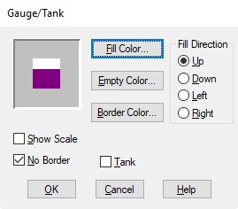
Gauge A vertical or horizontal sliding bar showing the location's current contents during the simulation (shown as a percentage of the capacity). This graph will be updated constantly as a simulation runs. The options available with gauges are explained below.
Tank A vertical or horizontal sliding bar showing the continuous flow of liquids and other substances into and out of tanks or similar vessels. This continuous modeling capability can be combined with discrete-event simulation to model the exchange between continuous material and discrete entities such as when a liquid is placed in containers.
Conveyor/Queue A symbol representing a conveyor or a queue. To create joints in a conveyor or queue, click on the conveyor or queue with the right mouse button. Drag the joints to achieve the desired shape. Right click on a joint to delete it. The options available with conveyors and queues are described next.
Label Any text used to describe a location. The label is initially synchronized with the name of the location and changes whenever the location name is changed. The name, size, and color of the text may be edited by double clicking on the label or selecting it and clicking on the edit button (see Text). Once the name on a label is edited, it will no longer be automatically changed when the location name is changed.
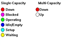
Status Light A circle that changes color during the simulation to show the location’s status. For a single capacity location, the states displayed are idle/empty, in operation, blocked, down, waiting, and in setup. For multi-capacity locations, the displayed states are up (operational) and down (off-shift, on break, disabled). Below are the states listed and their accompanying color:

Entity Spot An assignable spot on the layout where the entity or entities will appear while at the location. While an entity is at a location, the entity’s alignment spot (defined in the Graphic editor) will appear exactly on top of the location's entity spot, allowing the two graphics to align exactly as desired. A multi-capacity location will use as many entity spots as defined (in the order defined) up to the capacity of the location. Entities in excess of entity spots will continue to pile up on the last entity spot defined.
Region A boundary used to represent a location's area. A region may be placed in the layout over an imported background such as an AutoCAD drawing to represent a machine or other location. This technique allows elements in the imported background to work as locations.
Library graphic Any of the graphics appearing in the library graphic menu. Use the scroll bar to view all available graphics. Library graphics may be created or modified through the Graphic Editor. The name for the graphic, the default name of any location created with that graphic, can be saved in the Graphic Editor (see Naming a Graphic).
How to edit a graphic already on the layout:
or...
or...
Please Note: 1. Location graphics are painted on the layout in the order of the location list and, for any given location having multiple graphics, in the order that the graphic was added to the layout. 2. A location may include any of the above graphics and symbols. However, a location can have no more than one counter, one gauge, one tank, one queue, one status light, or one region. 3. Clicking on a layout graphic with no edit table on the screen displays the name of the element (location, etc.) represented by the graphic. With any edit table showing, hold down the CTRL key while clicking on the graphic to display the location name.
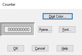
To edit the appearance of a counter, double click on the counter on the layout, select the counter and click on the Edit button, or right click on the counter and select edit. The counter dialog box allows you to choose the appearance of a graphic counter that is used to display the contents of a location. To change the digit color of the counter, click on the Digit Color button. To change the counter's background and border, click on the Frame button. The digit's font size and style may be changed by clicking on the Font button.
When you create a gauge or tank,
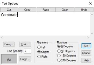
To edit the appearance of a location label, you may double-click on the text once it is on the layout, select the text and click on the Edit button, or right click on the text and select edit. The text is typed in an edit window with several edit features available via buttons above the window. The font, color, alignment, rotation and frame may be changed from this dialog box. A sample of the currently chosen options is shown in the lower-left corner.
To change or edit a library graphic that represents a location, you may double click on the library graphic on the layout, select the graphic and click on the Edit button, or right click on the graphic and select edit.
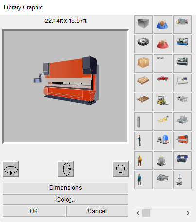
This gives the option to change the icon, orientation, color, or graphic dimensions of the graphic. The default dimensions for the graphic, which are created in the Graphic Editor, are displayed above the graphic. To change the dimensions of the graphic, click on the Dimensions button. This gives you the ability to specify horizontal or vertical and feet or meters to change the graphic dimensions.
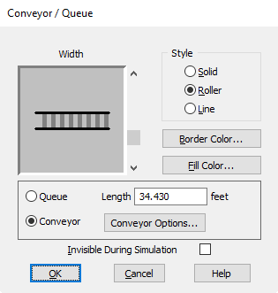
To control the look and operation of a conveyor or a queue, you may double click on the conveyor/queue in the Layout window, select the graphic and click on the Edit button, or right click on the conveyor/queue and choose edit graphic. The Queue/Conveyor dialog box appears. It also allows you to specify whether you wish to define the location as a conveyor or queue. Use the scroll bar to set the width of the queue or conveyor. Select the style by clicking on solid, roller (i.e., roller conveyor) or line. Click on the border color or fill color to change the color of the queue. If you want the queue to be visible during edit time and invisible during run time, click on the Invisible During Simulation option. See the discussion on conveyors and queues later in this section for more information.
A queue is a location that imitates the progressive movement and queuing of waiting lines. When an entity enters a queue,
If a Move statement is specified that includes a move time (e.g., Move for 5.2 sec), the entity speed and length of the queue are ignored. If a move time is not included with the Move statement, the move time is based on the entity speed and length of the queue (if no queue length or entity speed is defined, the move time is zero).
Entities in a queue may not be preempted by other entities and, once entities begin movement in a queue, are not allowed to pass each other. After the specified move time, however, entities continue processing any additional operation and output logic. A “No Queuing” rule specified for a queue location allows entities to depart in any order after completing their move time.
Queues are drawn from the beginning to the end of the center-line and are assigned a default length based on the graphic scale. However, the default queue length may be overridden by entering a different length. When a queue is modified graphically, the length will automatically be recalculated based on the graphic scale unless you checked the “Recalculate path lengths when adjusted” option. You can access this option from the Tools menu under Options.
A conveyor is a location that simulates the movement of entities on either an accumulating or non-accumulating conveyor and appears with a conveyor graphic. Entities can only enter a conveyor at the beginning and leave at the end. For accumulating conveyors, if the lead entity is unable to exit the conveyor, trailing entities queue up behind it. For non-accumulating conveyors, if the lead entity comes to a stop, the conveyor and all other entities stop. Entities on a conveyor may not be preempted by other entities.
The capacity assigned to a conveyor limits the number of entities that can access a conveyor. However, the cumulative total length or width of the entities on the conveyor cannot exceed the conveyor length. In fact, the utilization statistics for a conveyor reflect the amount of space utilized on the conveyor throughout the simulation, not the number of entities occupying the conveyor. Unlike other locations, an entity is not routed to the conveyor until there is room at the beginning for the entity to fit, even if the conveyor has capacity to hold it.
Move time on a conveyor is based on the length and speed of the conveyor, as well as the length or width of the entity. The move time for an entity on a conveyor is calculated using the following formula:
Time = (Conveyor Length - Entity Length or Width)/Conveyor Speed
And the percentage utilization is calculated using this formula:

Where:
tc = the time the entity spent on the conveyor whether moving or not
Cc = the conveyor capacity for that entity
T = the total simulation time
Please Note: Unlike queues, Move statements for conveyors may not include a move time. Processing logic executed at the end of the conveyor may contain any operation statement except for Create, Split As, Ungroup, or Unload. Additionally, the Accum, Combine, and Group statements are not allowed at the end of non-accumulating conveyors.
Due to the space limitations of a conveyor, certain operation statements at the beginning of a conveyor are invalid including Accum, Combine, Create, Group, Split As, Ungroup, and Unload.
The default conveyor length is determined by the graphic scale, although this may be overridden by entering a different length. When a conveyor is modified graphically, the length will automatically be recalculated based on the graphic scale unless you uncheck the “Recalculate path lengths when adjusted” option. You can access this option from the Tools menu under Options.
When you use conveyors and want the graphics to display properly on the conveyor with no overlapping and little space between entities, use the following:
|
Entity Orientation on Conveyor |
Requirements |
|
Width-wise |
1. Entity width on conveyor should equal horizontal dimension. |
|
|
2. Entity length on conveyor should equal vertical dimension. |
|
Length-wise |
1. Entity width on conveyor should equal vertical dimension. |
|
|
2. Entity length on conveyor should equal horizontal dimension. |
The animation of entities traveling along conveyors is displayed according to the logical length or width of the entity, not the scaled length or width of the entity graphic.
How to define a conveyor graphically:
How to create bends in an existing conveyor:
The conveyor options dialog box is used to define the specifications for a conveyor. To access the conveyor options dialog box, you may double click on a conveyor, select the conveyor and click on the Edit button from the Location Graphics window, or right-click on the conveyor and select edit. This opens the Conveyor/Queue dialog box from which the Conveyor Options dialog box can be opened by clicking on the Conveyor Options button. The Conveyor Options dialog box presents the following options:
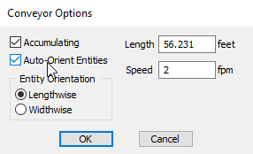
Accumulating Select or deselect this option depending on whether the conveyor is to be accumulating or non-accumulating.
Auto-Orient Entities In new conveyors, the option is automatically selected. When selected, entities will auto orient along the conveyor based on the selected Entity Orientation; Entities will lead from the right side of the graphic when Widthwise is selected, top of the graphic when you select Lengthwise.
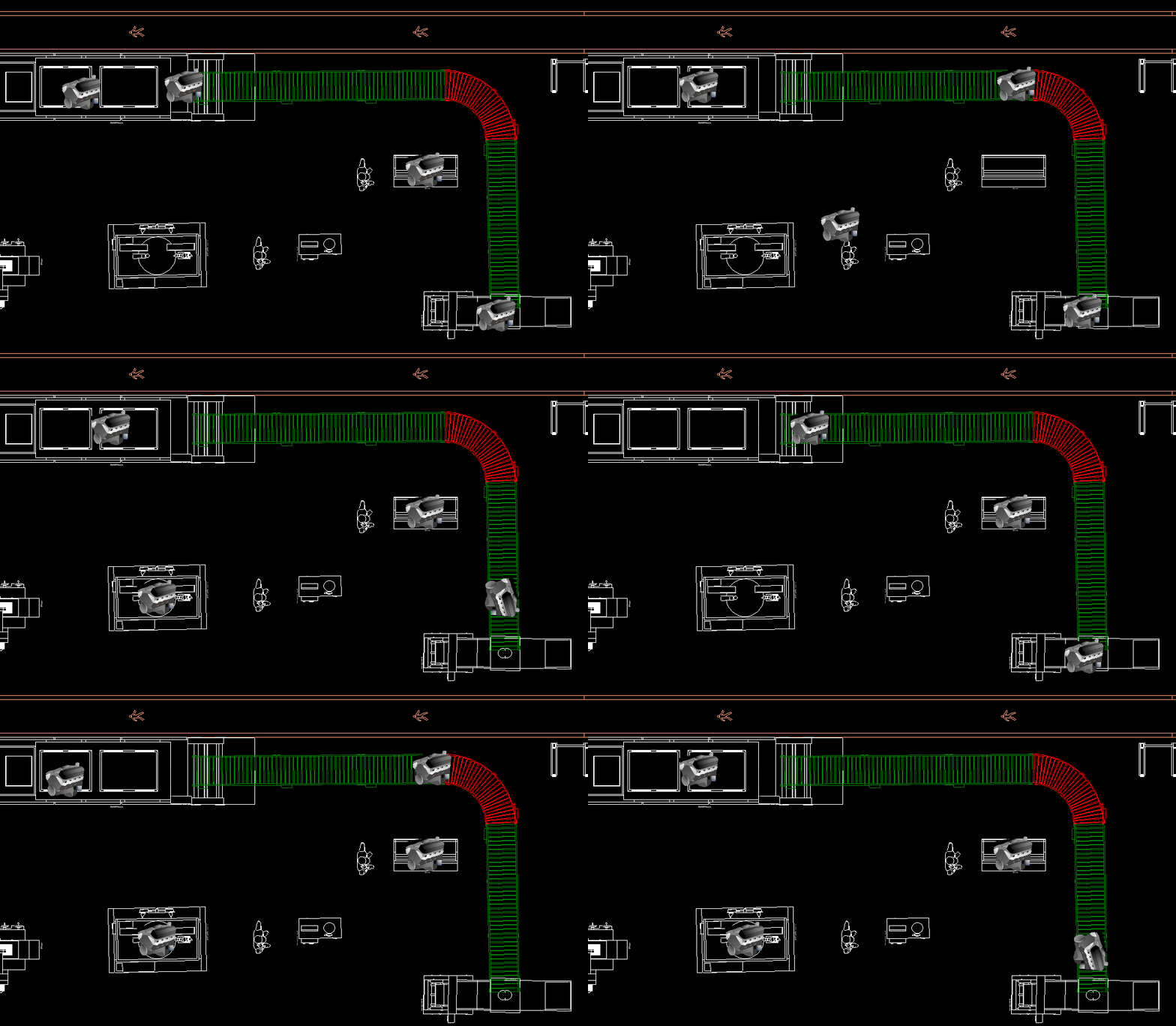
Entity Orientation Select Lengthwise or Width-wise depending on whether the entity is traveling on the conveyor in the direction of the entity length or in the direction of the width.
Length The length of the conveyor expressed in either feet or meters depending on the default specified in the General Information dialog.
Speed The speed of the conveyor in feet or meters per minute. The distance units can be set in the General Information dialog box.
|
© 2019 ProModel Corporation • 705 E Timpanogos Parkway • Orem, UT 84097 • Support: 888-776-6633 • www.promodel.com |