The Graphic Tools Button Bar contains the tools necessary to create and edit a graphic’s component objects. The drawing tools are the main tools through which graphics are created and edited in the Editing window. The drawing tools include the following:
| Selector |
|---|
| Text |
| Lines |
| Arcs |
| Triangles |
| Regular Squares and Rectangles |
| Rounded Squares and Rectangles |
| Circles and Ellipses |
| Chords |
| Pies |
| Polygons |
| Raised Squares and Rectangles |
| Entity Spots |
| Status Lights |
| Flip Horizontal |
| Flip Vertical |
| Rotate |
| Cut |
| Copy |
| Paste |
| Step Back |
| Step Front |
| Line Color |
| Fill Color |
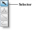
The Selector is a pointing device that allows you to select one or more objects of a graphic. It also allows you to move, size, and shape all graphic objects.

How to move an object:
How to size or shape an object:
Text may be placed anywhere in the graphic by using the Text tool.
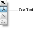
How to place text in a graphic:
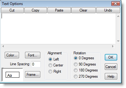
How to edit text already in the graphic:
Lines may consist of several segments and are drawn using the line tool.
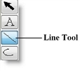
How to draw lines in the graphic editor:
Please Note: Lines can be drawn at 15 degree increments by holding the shift key while moving the end of a line segment.
Arcs are drawn using the Arc tool.

How to draw an arc in the graphic editor:
Please Note: To have the arc bow left, start the arc from the top and drag down. To have the arc bow right, start the arc from the bottom and drag up.
Triangles are drawn using the Triangle tool.
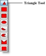
How to draw a triangle in the graphic editor:
Squares and rectangles may be drawn using the regular rectangle tool, the rounded rectangle tool, or the raised rectangle tool.
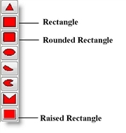
How to draw a rectangle in the graphic editor:
How to draw a square in the graphic editor:
Circles and ellipses may be drawn using the ellipse tool.
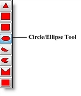
How to draw an ellipse in the graphic editor:
How to draw a circle in the graphic editor:
Chords and pies are drawn using the Chord tool and Pie tool.
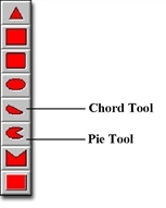
How to draw a chord or pie in the graphic editor:
How to draw a circular chord or pie in the graphic editor:
How to adjust the size of the “slice” in the chord or pie after the graphic has been drawn:
Polygons are drawn using the Polygon tool.
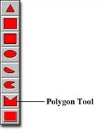
How to draw a polygon in the graphic editor:
Please Note: The sides of a polygon may be drawn at 15 degree increments by holding down the shift key while moving the mouse to the next vertex.
A positioning spot controls the positioning of an entity on a location, resource, or path. It also controls the positioning of an entity or resource on a path. There are two types of positioning spots: entity spots and alignment spots.
Entity spots can be defined for a graphic in either the Graphic Editor or in the Locations module. Alignment spots can only be defined for a graphic in the Graphic Editor. In the Graphic Editor, the button showing the red circle with the white X represents the positioning spot. The default type is entity spot. To change the type, the user may double click on the spot to display the Spot Type dialog. This allows the user to define the type of positioning spot.
A graphic may have any number of entity spots. A graphic may also have any number of alignment spots. However, only the first alignment spot defined will be used. An entity or alignment spot is ignored if it is inapplicable for the model element it is used to represent. The following definitions explain uses of the entity and alignment spots for locations, entities, and resources.

How to place a positioning spot on an icon:
Location Graphics May only use entity spots. Whenever an entity arrives at the location, the entity graphic will be placed on the first entity spot defined for the location. The next arriving entity will use the entity spot defined second, and so forth. If entity spots are defined for a location graphic in the Locations module, they are used ahead of any entity spots defined in the Graphic Editor. If no entity spot is defined for the location graphic, no entity is shown on the location.
Entity Graphics Use only alignment spots. When an alignment spot is defined for an entity graphic, the entity graphic will be positioned so the alignment spot of the entity graphic and the entity spot for the location or resource graphic are aligned. If the entity is traveling along a path, the entity graphic will move along the path with the alignment spot and the path segment or node aligned. If no alignment spot is placed on an entity graphic, the center of the entity graphic is used for alignment.
Resource Graphics May use both entity spots and alignment spots. An entity spot on a resource graphic may be used to locate an entity a resource is carrying. An alignment spot can be placed on a resource graphic so that when the resource travels along a path, the resource graphic will move along the path with the alignment spot and the path segment or node aligned. If no alignment spot is placed on a resource graphic, the center of the graphic is used for alignment.
A status light is a circle that changes color depending on the status of a location. A status light can be placed anywhere relative to a location to show the status or current state of the location. At run time, a window can be displayed showing what status each color represents.

How to place a status light on an icon:
Please Note: Status lights for location graphics may also be defined in the Locations Editor.
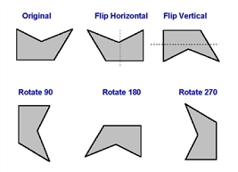
Objects may be flipped about the horizontal axis and vertical axis or rotated by 90 degrees using the flip and rotation tools from the Tools button bar.

How to flip or rotate an object:
Using the flip and rotate buttons is the same as choosing flip and rotate options under the Graphics menu.
The figure below shows an object that has been flipped horizontally, vertically, and rotated through all phases.
To speed the development of complex graphics, you may cut, copy, and paste objects from one area of the workspace to another. Each of these buttons works exactly the same as the corresponding item from the Edit menu.

How to cut an object:
How to copy an object:
How to paste an object:
You can move an object behind or in front of another object. The Step Back option allows you to move a selected object behind another object. The Step Front option allows you to move a selected object in front of another object.
For example, suppose you have five graphic objects displayed and you want to move the top object to the third object. You can use the Step Back or Step Front option.

How to move an object behind or in front of another object:
Please Note: If you would like to move an object behind or in front of all objects, use the Move to Back or Move to Front option in the Graphics Menu. Alternatively, use the Page Up or Page Down keys.
An object’s line and fill colors can be chosen using the Line tool and the Fill tool. You may use one of the predefined colors or create your own custom color. Each tool’s color changes according to the color chosen.

How to define the line color or fill color:
Please Note: The line color and fill color can also be defined in the Graphic Editor Options menu.
|
© 2019 ProModel Corporation • 705 E Timpanogos Parkway • Orem, UT 84097 • Support: 888-776-6633 • www.promodel.com |