This discussion covers the procedures used to define operations and routings using the Processing Editor. As with most other procedures in
Before you begin to specify the processing logic, define all locations and entities to be referenced in the processing. This is done through the Location and Entity Editors. If you reference a location or an entity that has not yet been defined in a location or entity field, you will be prompted to add that location or entity to the respective location or entity list. However, no graphic gets automatically assigned to the location or entity.
The easiest way to define the processing logic is to define the routing or flow sequence using the tools in the Processing Tools window, which appears in the lower left corner of the Processing Editor. These tools have been designed to allow you to easily and rapidly define the flow of entities through the system. It is also a good idea to define the routing rule for each routing as it is created. Once you have defined the from-to relationships between locations for each entity, fill in the details of the operation and move logic for each location. This is typically done by typing the logic in the operation or move logic column manually or by using the Logic Builder, documented at the end of this section.
Defining processes graphically in
Process Edit Table
Routing Edit Table
Tools Window
Layout Window
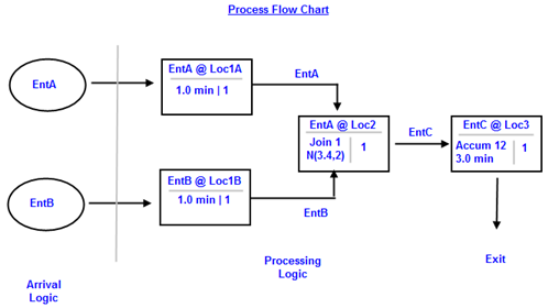
Before discussing the procedures for using these windows interactively, let us look briefly at a process flowchart of a simple model.
In the flowchart above, each block represents a process record for an entity at a location. The lower left portion of a block specifies the operation(s) performed on the entity at the location. The lower right portion of the block represents the number of entities output to the next location.

|
© 2012 ProModel Corporation • 556 East Technology Avenue • Orem, UT 84097 • Support: 888-776-6633 • www.promodel.com |